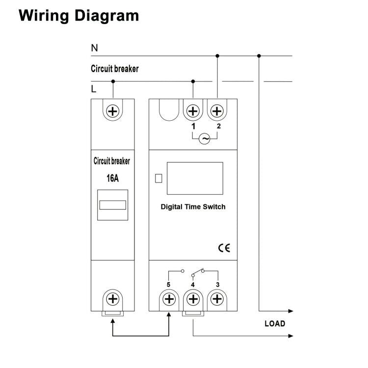
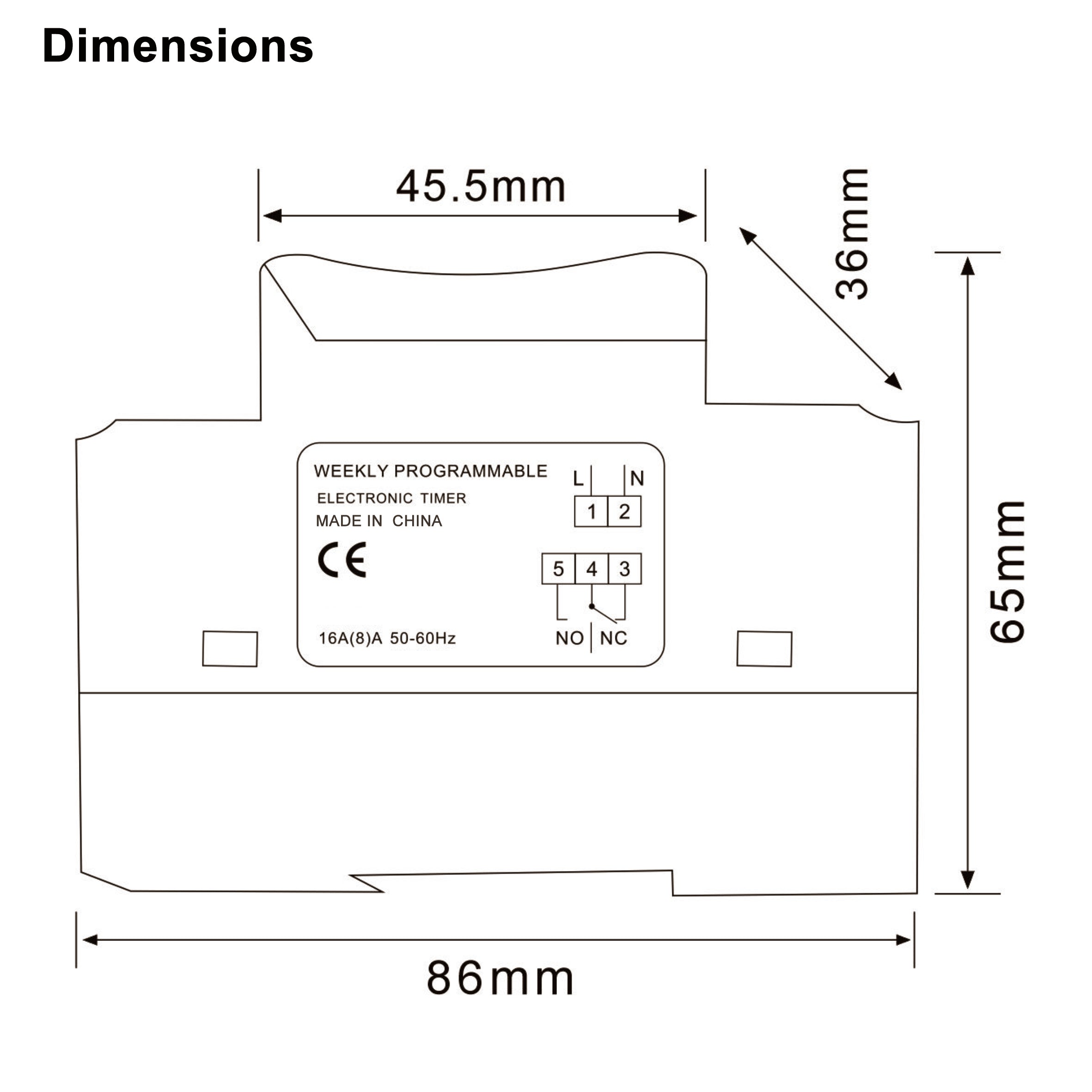
The wiring diagram doest make sense.
I have a 220 volt electric heater that I need to cycle off at night and back on in the morning. Simple. The diagram shows a circuit breaker with both legs going to the timer along with a NEUTRAL. It's the exact same diagram for all voltages. I don't mind just breaking one leg to the heater and leaving the other live in order to make it work.
There are THREE wires going to the timer. The diagram shows the LOAD wire going to the common of the no/nc terminals. The LINE wire should go to the common #4 terminal and then depending what you want, your LOAD wire should be connected to the normally open #5 or normally closed #3 terminal.
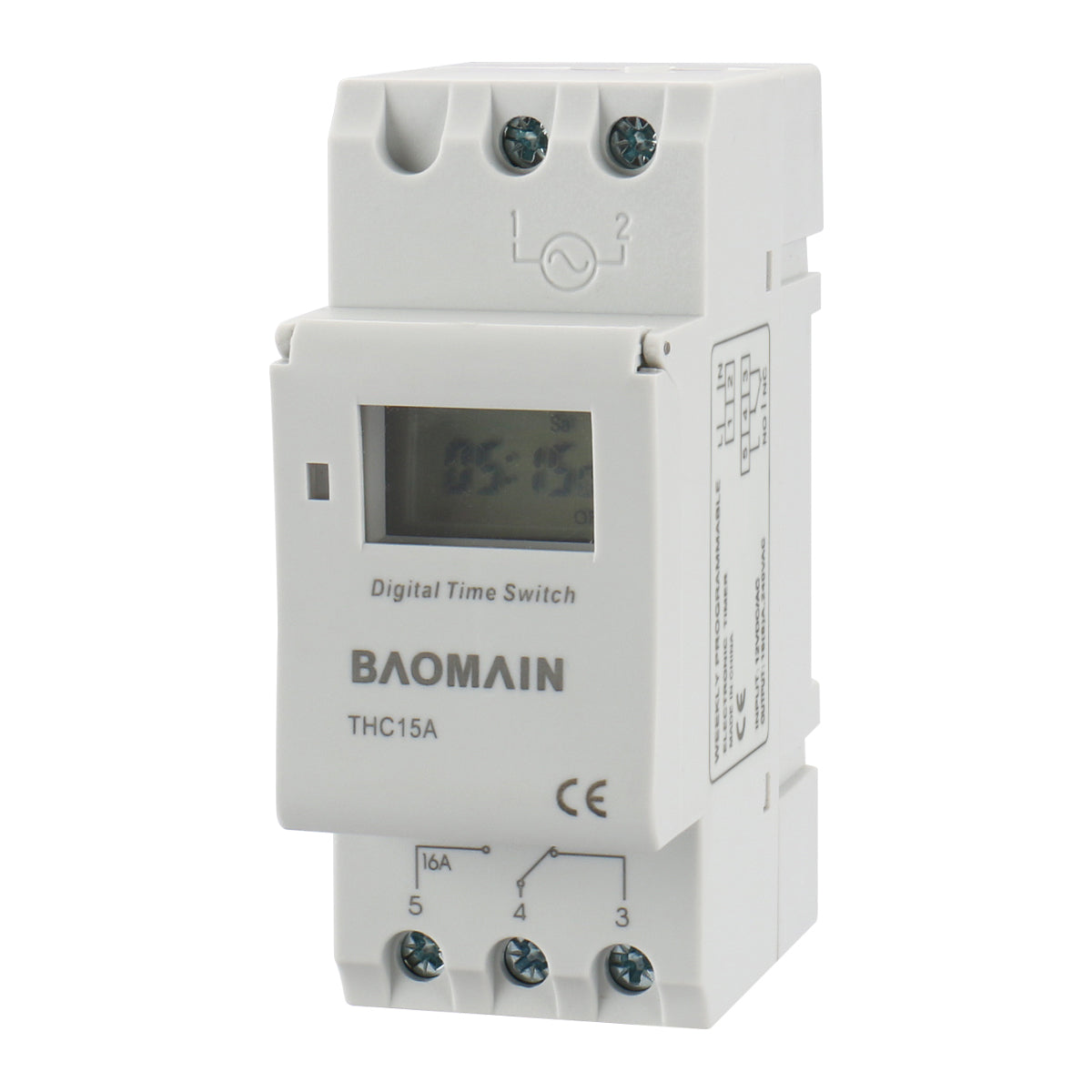
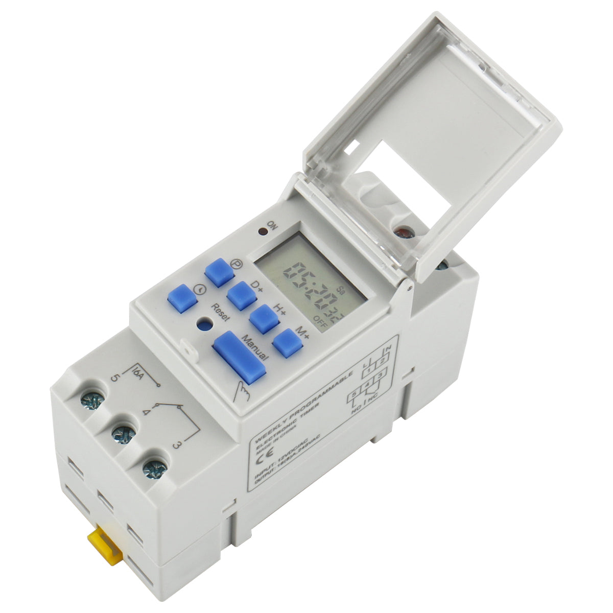
On top of the timer are 2 terminals. It shows a LINE wire connected to terminal #1 and a NEUTRAL wire connected to terminal #2. Both of which continue to the device. What are those two terminals on top for? Are they to power the timer and the battery is a back-up?
I've been winging controls and relays for 45 years and this is just weird. Or maybe it's me?
It would be great if someone could clarify this for me. Programming the timer was pretty straight forward.